
Hub and spoke on AWS: from architecture to the actual traffic path
Follow the outbound and return paths of a connection using centralized AWS egress and see how Transit Gateway route tables separate environments.
Consider an application in a private production subnet that needs to access a public API. The VPC is connected to the Transit Gateway, the attachment appears to be available, and the central network account has a NAT Gateway. The connection, however, ends in a timeout.
To locate the failure, you need to follow the tables that forward the request and the ones that bring back the response. The attachment connects the VPC to the central router. The routes determine what happens to each packet after that connection.
In a hub-and-spoke architecture, the spokes are the application networks connected to a central point. On AWS, the Transit Gateway (TGW) acts as a regional router between networks. A central VPC can concentrate internet egress while applications remain in their own accounts and VPCs. For this design to work, the TGW routing decisions must work together with the decisions inside each VPC.
Three VPCs and one communication policy
The example uses three VPCs in a single Region, spread across one network account and two application accounts. The names and addresses are fictitious.
| VPC | CIDR | Role |
|---|---|---|
| Production | 10.240.0.0/16 | Applications in private subnets |
| Development | 10.241.0.0/16 | Applications in private subnets |
| Central egress | 10.242.0.0/16 | Forwarding to NAT and the internet |
Production and development need to initiate connections to public destinations. Communication between their private addresses must be blocked. Each VPC has an attachment to the same TGW.
In the central VPC, traffic arrives through a subnet used by the attachment and proceeds to a public zonal NAT Gateway, installed in a public subnet. That subnet has a route to an Internet Gateway. The example follows one Availability Zone (AZ) and does not include an inspection firewall.
The intended path is:
Application -> TGW -> Egress VPC -> NAT Gateway -> Internet Gateway -> Public API
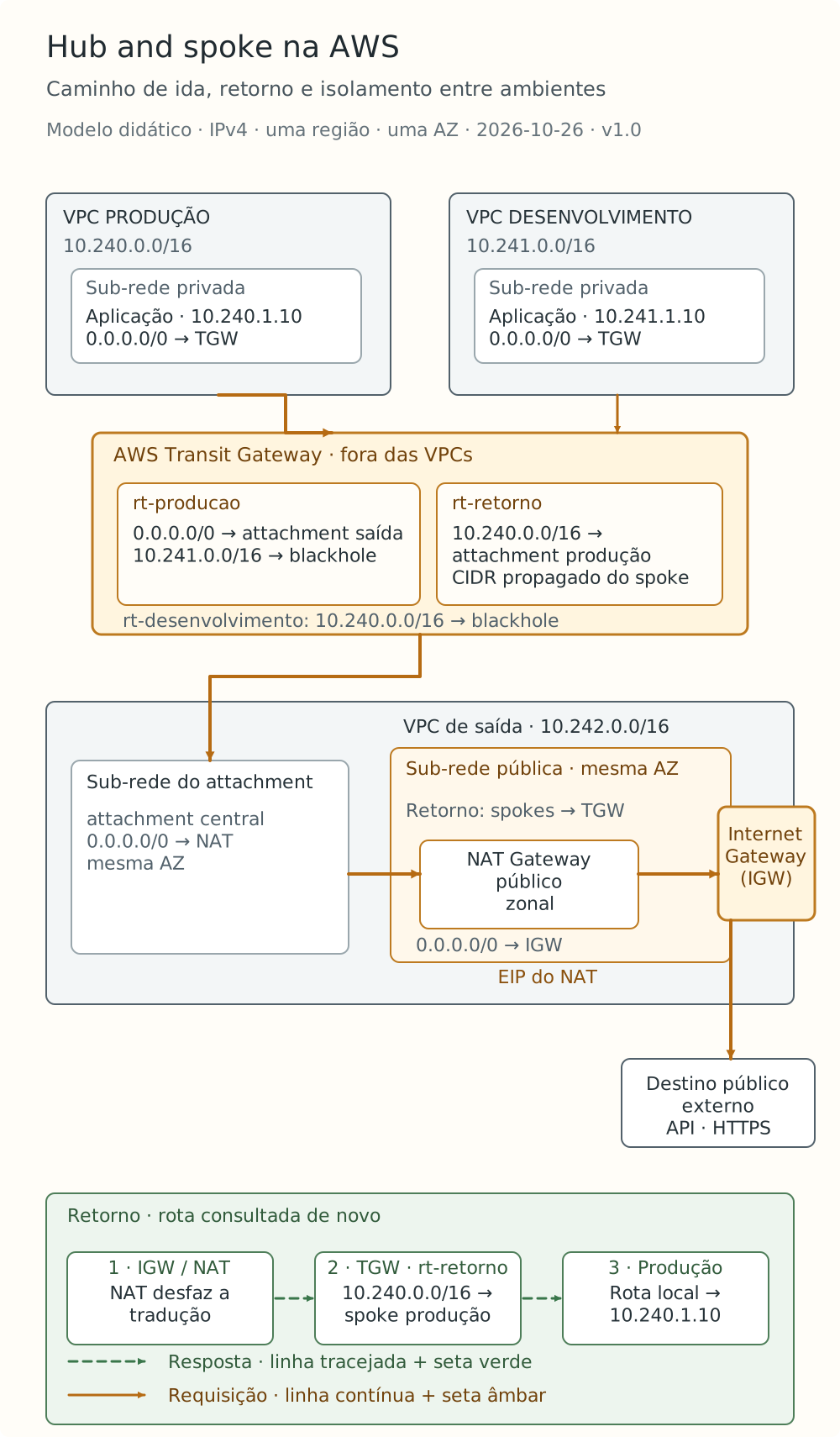
Didactic IPv4 example. The figure follows one AZ and does not represent a customer environment. Diagram labels are in Portuguese.
Which table does the TGW consult?
When the packet enters the TGW, the table consulted depends on the attachment through which it arrived. This choice is defined by the association: each attachment can be associated with one and only one TGW table.
Propagation has a different function. It installs routes from an attachment in the selected tables. For VPC attachments, the VPC CIDR blocks can be propagated to one or more tables. These rules are described in the TGW association and propagation sections.
In this example, the relationships are explicit and do not depend on the default associations and propagations:
| Attachment | Associated table | Where the VPC CIDR propagates |
|---|---|---|
| Production | rt-producao | rt-retorno |
| Development | rt-desenvolvimento | rt-retorno |
| Central egress | rt-retorno | No table |
A packet arriving from production consults rt-producao. A packet arriving from the egress VPC consults rt-retorno. Therefore, the request and response cross the same TGW using different tables.
Propagating the spokes into rt-retorno lets the TGW know the private destinations to which it must return traffic. It does not create routes in the VPC subnets: that part must be configured separately.
From the private subnet to the central NAT
The production application has the address 10.240.1.10. To initiate a connection to a public destination, the table associated with its subnet contains:
| Destination | Target |
|---|---|
10.240.0.0/16 | local |
0.0.0.0/0 | Transit Gateway |
Traffic within the VPC uses the local route. All other destinations go to the TGW. In development, the structure is the same, with 10.241.0.0/16 as the local CIDR. The documentation on VPC routes for gateways and connections details this configuration.
The TGW tables receive the following routes:
| Table | Destination | Target or action | Type |
|---|---|---|---|
rt-producao | 10.241.0.0/16 | blackhole | Static |
rt-producao | 0.0.0.0/0 | Central egress attachment | Static |
rt-desenvolvimento | 10.240.0.0/16 | blackhole | Static |
rt-desenvolvimento | 0.0.0.0/0 | Central egress attachment | Static |
rt-retorno | 10.240.0.0/16 | Production attachment | Propagated |
rt-retorno | 10.241.0.0/16 | Development attachment | Propagated |
blackhole routes discard the corresponding traffic, according to the TGW static routes and blackholes mechanism. The rationale for these blocks appears below. For now, follow the connection to a public address: it matches the default route in rt-producao and leaves through the central attachment.
When it reaches the egress VPC, the packet begins following the table of the subnet used by the attachment. For the AZ followed in the example, the tables are:
| Central VPC table | Destination | Target |
|---|---|---|
| Attachment subnet | 10.242.0.0/16 | local |
| Attachment subnet | 0.0.0.0/0 | NAT Gateway in the same AZ |
| NAT public subnet | 10.242.0.0/16 | local |
| NAT public subnet | 10.240.0.0/16 | Transit Gateway |
| NAT public subnet | 10.241.0.0/16 | Transit Gateway |
| NAT public subnet | 0.0.0.0/0 | Internet Gateway |
The first table takes the connection to the NAT. The second lets it continue to the Internet Gateway and also contains the spokes' return routes. This chain follows the centralized IPv4 egress pattern documented by AWS.
At the public NAT, the application's private address is translated to the NAT Gateway's private address. The Internet Gateway maps it to the associated Elastic IP. This is the public address that participates in communication with the API. In the response, the translations are reversed, as explained in the NAT Gateways documentation.
The return is a second routing decision
After the return translation, the destination becomes 10.240.1.10 again. The next hop must carry this packet to the production VPC.
In the NAT public subnet table, the 10.240.0.0/16 -> TGW route is more specific than 0.0.0.0/0 -> Internet Gateway. It is therefore selected. The most-specific-prefix priority rule is what keeps the response on the private path.
The packet re-enters the TGW through the central VPC attachment. This time, the table consulted is rt-retorno. The propagated 10.240.0.0/16 route points to the production attachment. Once it enters that VPC, the traffic uses the attachment subnet's local route to reach the application, subject to access controls.
Now consider two possible failures:
- Without the production route in the NAT public subnet, the response may follow the default route to the Internet Gateway.
- Without the production route in
rt-retorno, the TGW cannot find a path to the spoke attachment.
In both cases, the outbound configuration may appear correct. The application still times out because the response does not complete the path.
The default route can create a detour between environments
The 0.0.0.0/0 route also matches private addresses when there is no more-specific route.
Imagine removing the development blackhole from rt-producao while keeping the other tables. A production packet to 10.241.1.10 then follows the default route to the central VPC. From there, it may reach the NAT and be forwarded back to the TGW, now through the central attachment. rt-retorno knows the development CIDR.
This NAT detour is described in the blackholes section of the AWS centralized egress example. Not propagating development into rt-producao prevents a direct route in that table, but it does not demonstrate that every path between the VPCs is blocked.
In our example, 10.241.0.0/16 -> blackhole discards this destination before it follows production's default route. The reverse entry in rt-desenvolvimento blocks private access to production.
These entries cover both CIDRs presented here. New VPCs, secondary CIDRs, VPNs, and other connections require the policy to be reviewed. The return table knows both environments; its association and propagations must remain controlled as the network grows.
Filters remain part of the configuration. Security groups are stateful and control traffic for associated resources. Network ACLs are stateless and require rules compatible with both directions of communication in the involved subnets. An existing route is not equivalent to an allowed connection.
How to check the path without relying on a timeout
Start with one specific connection: source, destination, protocol, and port. In the example, the application 10.240.1.10 might initiate TCP on port 443 to a public test destination. With that reference, follow the forwarding order:
- Check the table actually associated with the source subnet and the route selected for the destination.
- Check the attachment state and the enabled AZs. A resource in an AZ without an attachment subnet cannot reach the TGW, even with a route pointing to it. This is one of the VPC attachment requirements.
- Consult the TGW table associated with the incoming attachment and identify the next attachment or blackhole.
- Follow the central VPC tables, from the attachment subnet to the NAT and Internet Gateway.
- Repeat the analysis for the return, using the private destination restored by the NAT and the table associated with the central attachment.
- Check traffic controls and whether the destination service is available for that connection.
A successful outbound test still leaves the separation between environments unanswered. Verification of the example must include both the allowed and prohibited attempts:
| Source | Destination | Expected result |
|---|---|---|
| Production | Public test destination, HTTPS | Connection completed with a response |
| Development | Public test destination, HTTPS | Connection completed with a response |
| Production | Private development address | Discard at the expected blackhole |
| Development | Private production address | Discard at the expected blackhole |
A timeout by itself does not identify where the block occurred. In negative tests, it may result from a missing route, a filter, or destination unavailability. To attribute the result to the blackhole, compare the effective route with flow evidence, using the same addresses, ports, and time interval.
TGW Flow Logs record traffic information in the Transit Gateway, while VPC Flow Logs record information about VPC interfaces. Collection and publication are delayed, so the immediate absence of a record does not end the investigation.
Reachability Analyzer can help find configuration blocks on supported paths. It builds a network model without sending packets or analyzing the data plane. For TCP that crosses TGW tables, there is another limitation: only the outbound direction is analyzed. The service documentation records this restriction, which makes separate verification of the return especially relevant here.
The table results are expectations for the didactic scenario. The example was not provisioned or subjected to traffic tests for this article.
As the network grows, revisit Availability Zones and costs
The path was shown in one AZ to make the tables easier to read. With zonal NAT Gateways, placing applications in multiple zones while keeping a single NAT concentrates the egress dependency. To improve this model's resilience, AWS recommends using one NAT per AZ with same-zone routing.
The zonal model is not the only available option. Regional NAT Gateways have a different availability arrangement and use their own table, without requiring a public subnet to host them. The tables presented here belong to the zonal example and must be reviewed if this choice changes.
Centralization also changes the cost composition. The TGW has charges for attachments and data processing, in addition to the other components in the path. Reducing the number of NATs may lower one portion of the bill, but that count alone does not demonstrate savings. Traffic volume and path must be included in the comparison.
A useful review of this design follows one connection through its response and identifies the table responsible for each decision. Then it attempts the paths that should be blocked. This combination is what lets you assess whether routing implements the communication policy defined for the environments.